Search  for anything...

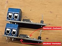
6PCS Dual High-Power MOSFET Trigger Switch Drive Module 0-20KHz PWM Adjustment Electronic Switch Control Board Motor Speed Controller Lamp Brightness Control, DC 5V-36V 400W, 15A (Max 30A)

  • Based on 19 reviews
Condition: New
Checking for product changes

Buy Now, Pay Later


As low as $2 / mo
  • – 4-month term
  • – No impact on credit
  • – Instant approval decision
  • – Secure and straightforward checkout

Ready to go? Add this product to your cart and select a plan during checkout.

Payment plans are offered through our trusted finance partners Klarna, PayTomorrow, Affirm, Afterpay, Apple Pay, and PayPal. No-credit-needed leasing options through Acima may also be available at checkout.

Learn more about financing & leasing here.

Selected Option

Free shipping on this product

30-day refund/replacement

To qualify for a full refund, items must be returned in their original, unused condition. If an item is returned in a used, damaged, or materially different state, you may be granted a partial refund.

To initiate a return, please visit our Returns Center.

View our full returns policy here.


Availability: In Stock.
Fulfilled by Amazon

Arrives Thursday, Jun 26
Order within 14 hours and 55 minutes
Available payment plans shown during checkout

Style: 6PCS


Features

  • Working voltage: DC 5V-36V, the trigger source: digital high-low (DC 3.3V - 20V), continuous current: 15A, maximum current and power: 30A, 400W, operating Temperature: -40-85C, size: 1.34x0.67x0.47inch/34 x 17 x12mm (length x width x height)
  • DUAL MOS DRIVE: The MOSFET motor board Utilizes dual MOS parallel connection with active output, featuring lower internal resistance, higher current, and robust power output (15A, 400W at room temperature), meeting the requirements of most devices
  • WIDE VOLTAGE RANGE, PWM SUPPORT: With a working voltage range of DC 5V to 36V and compatibility with PWM signals, this PWM regulator control panel offers versatility in controlling devices. It accepts digital signals within the voltage range of DC 3.3V to 20V, making it suitable for use with micro controller IO ports, PLC interfaces, and other DC power sources
  • COMPACT DESIGN, EASY INTEGRATION: Measuring just in 34x17x12mm (1.34x0.67x0.47inch), this high power PWM MOSFET driver module offers a compact form factor, facilitating effortless integration into various applications. Easily achieve control over high-power devices with this versatile and efficient module
  • WIDELY APPLICATIONS: The MOSFET switch drive module is a versatile power control module that excels in a wide range of applications. Its design allows for precise control of high-power devices such as motors, LED lights, bulbs, micro-pumps, and solenoid valves. By accepting PWM signals, it can accurately regulate motor speeds, adjust lamp brightness, and more

Color: Blue


Brand: Seloky


Material: Plastic


Manufacturer: Seloky


Package Dimensions: 5.1 x 3.5 x 0.59 inches


Item Weight: 1.76 ounces


Manufacturer: Seloky


Country of Origin: China


Batteries required: No


Included Components: MOSFET


Frequently asked questions

If you place your order now, the estimated arrival date for this product is: Thursday, Jun 26

Yes, absolutely! You may return this product for a full refund within 30 days of receiving it.

To initiate a return, please visit our Returns Center.

View our full returns policy here.

  • Klarna Financing
  • Affirm Pay in 4
  • Affirm Financing
  • Afterpay Financing
  • PayTomorrow Financing
  • Financing through Apple Pay
Leasing options through Acima may also be available during checkout.

Learn more about financing & leasing here.

Top Amazon Reviews


  • Very Cool MOSFET Driver Modules - Fun To Use!
Style: 12PCS
Q: What Are These Things? A: These MOSFET modules let you control various types of loads that require greater current and/or voltages then the device (i.e. microcontrollers, etc) can directly drive. SHIPPING: I was warned that these would take a long time to arrive, and they weren’t kidding: 30+ days! FORMAT: Arrived in a 4x3 panel inside a standard plastic pouch which is not static proof. They easily snap into individual modules. FOR CLARITY: The item page mentions “POWERFUL ESP32-C3" in a way that implies that this device has such a MCU, which it does not. I won’t speculate as to why they mention it, but it should be ignored as such a reference is superfluous. WHAT TO KNOW: Q: What’s going on with 2 sets of 3 holes on J1? A: These are split into 2 groups of 3, where 3 are TRIG/PWM and 3 are GND. There are several ways to wire this module. Take a look at the pictures for details. I chose a 3-pin 0.10” on center header with the center cutoff at the PCB. I show examples in the photos - take a look! Q: Is the control signal (TRIG/PWM) GND separate from the load voltage’s power supply “VIN-“? A: NO, both the “VIN -“ & the control signal GND are tied together. NOTE: This circuit “pulls down” the load to GND. This is similar to an NPN Open Collector circuit. Q: Are the MOSFETS wired in parallel? A: YES! Both G, D, S, pins are tied together between both MOSFETs. This increases the modules’ current sinking capability by a factor of 2. Be mindful of heat dissipation. I didn’t test these anywhere near their max current specs. Q: Will this filter any noise from being back fed from the load into the control (TRIG/PWM) and load power supply circuits? A: NO: Not at all! A noisy load, like a motor or relay, will create all kinds of noise which will be happily back fed into the GND, TRIG/PWN, and VIN+ lines! I suggest inserting a “pie” filter in between the load and the VOUT - & VOUT + terminals to help clean that noise up - probably put it as near as possible to the motor/relay! Q: Is there a schematic? A: NOT THAT I’VE FOUND. But, hey, it’s a simple design and easily “buzzed” if you care enough to do so. Q: Is this device active high or low (i.e. what voltage at the Gate turns on the load?) A: This is an N-Channel MOSFET so a positive voltage at the Gate will enable it, therefore, this is an ACTIVE HIGH device. When a PWM signal is present at TRIG/PWM input the device will be enabled during the POSITIVE part of the duty cycle. Q: Is a resistor needed between the control signal source and the TRIG/PWM input? A: NO, there is a 56 ohm (“56R”) resistor already in series between the TRIG/PWM and the 2 MOSFET Gates. Q: What is the lowest TRIG/PWM control signal level? A: I was able to get these to work down to 3.0VDC, but you should stick to the minimum 3.3VDC level! Anything lower and you risk running the MOSFETs in a non-switching mode: not what you want with these bad puppies! Q: What is the PWM frequency range? MFG states “20kHz”. A: YES, these work to 20kHz, at least on a purely resistive load. See TEST NOTES and the numbered pictures for an example at 20kHz. Q: Will the module heat up during usage? A: Probably, but not by much at lower current levels. I’ve included a couple IR photos to the resistive load and the module at 500mA at 10VDC to the load for reference. There about a 20F difference between them. TEST NOTES: I tested this with both a little DC motor and a 10 ohm (10R) 100W resister network as shown in photo (0). You can see that it does a pretty good job of translating the 5V 50% duty cycle square wave PWM input signal to a 10V output. RINGING! OK, about that ringing you see at the low side: that’s not the modules fault, it’s result of my mismatching cable impedances. The signal generator’s output is split with its 1st leg of the single sent to the o-scope [photo (3)] via 50 ohm cable and the 2nd leg sent to an unbalanced pair of test clips, plus there’s the 2nd pair of probe test un-balanced test leads feeding the 2nd o-scope in photo (4). So, don’t blame the module for that ringing noise. CONCLUSION: These are very useful when connecting a low power (example 5VDC or 3.3VDC microcontroller) device to a higher power (example: motor running at 16VDC at 1.5A). The soldering and PCB assembly looks solid. The device behaves as expected. For folks that don’t want to build their own PCBs this can be a real time saver! So, are these worth the wait? YES! I can recommend these MOSFET PCBs. Very fun and useful modules! ... show more
Reviewed in the United States on May 11, 2025 by Pike City Pike City

  • Works as listed with one caution...
Style: 12PCS
This review is for the "12PCS Dual High-Power MOSFET Trigger Switch Drive Module 0-20KHz PWM Adjustment Electronic Switch Control Board Motor Speed Controller Lamp Brightness Control, DC 5V-36V 400W, 15A (Max 30A)." My only caution here is that you don't max out the current specs. These MOSFETs will fry. However, they work very well at moderate currents. These don't have heat sinks, so if they get hot for you, it may not be a bad idea to put a fan on them to help dissipate the heat. The MOSFETs used in this DC switch have very low on resistance. Sometimes manufacturers will use MOSFETs with nominal or even high enough resistance I have to adjust input voltage to accomodate power loss. Not these gems. I especially like that I can use a PWM signal on these to control LED brightness or Fan speed on fans without a PWM input.p If you need this type of switch for your DC projects that require a 3.3V super low load trigger voltage, these may do you well. I'm using them now to test my microprocessor based projects because they work really well and are well made. The only missing item in this otherwise awesome deal are the two or four pin headers for the trigger input and ground. You only need two pins, but it has room for four in case you need to cascade them. Recommended product. Great value. ... show more
Reviewed in the United States on May 12, 2025 by Signus

  • High quality fabrication and average quantity pricing
Style: 12PCS
Review of ”400W Dual High-Power MOSFET Trigger Switch Driving Module DC 5V-36V 15A...": (Please refer to my reviewing guidelines at the bottom of the page). These are nicely fabricated MOSFET boards. The components are well placed and the solder flow was well done. They work as expected as long as you know what to expect. I have included a circuit diagram of the boards and the following are a few pointers to help with your expectations. 1) These are low side (N-Channel) MOSFETS so the ground side is what is switched and the positive side remains common to the input positive. This will work fine as long as it's not switching something that is in a circuit where the ground needs to be common with other devices in the circuit. For example; you can run a motor, solenoid, LED, or whatever as long as the negative output from this device is the only negative connection to the device you are running. 2) You must stay below the input current capability of the MOSFET maximum gate current. A current limiting resistor in series with the trigger input needs to be calculated for the voltages you are operating at and used or you will destroy the MOSFET. 3) There is no built-in protection for the MOSFET output. If to are driving any type if inductive load like a motor, relay, light bulb, solenoid, or whatever you must install a flyback diode in parallel with the output. 4) They promote the capability of driving 400 watts with proper heat dissipation but the MOSFETs will not survive very long any where near those loads. If you are biasing the gate properly to switch a load full on and full off with PWM at a certain frequency the heat dissipation is not as critical as if you are not switching full on/off. But in either case I would highly recommend mounting heat sinks to the MOSFETS if driving anything over about 50 watts and try not to exceed a 150 watts maximum if you want reliability and longevity of the circuit. 5) Contrary to other reviewer feedback, the screw terminals mounted to the board are rated at a maximum 300V/10A and the circuit board traces for the current path are robust so that should not be a limitation for you. I've done a bit of market research on Amazon for this specific type of product and find that the current price of $13 ($1.08 each) is close to the middle of the pricing range for a quantity of 12, so it is fairly priced for the market. I am assigning 4 stars due to the high quality fabrication and average pricing. I would assign 5 stars if the pricing were more competitive. My responsibility as an Amazon Vine Reviewer: Considering the Amazon rules/regulations for being a Vine Member It is obvious that it is very important to Amazon that the person doing the review has indeed inspected, tested, used the product as well as being aware of the competitive situation of the market segment. This is so it can be fairly compared and reviewed whether good, bad, average, or anywhere in all of the grey area between. One thing that I wish were better defined by Amazon is exactly what each star should represent from 1 to 5 so that every Vine member would use the same guide in that regard. So, to let you know the guide that I use, I include it as follows: I always start off considering that average is 3 stars, and an average rating to me is: The product was correctly represented in the ad. The manufacturing quality is as expected. The product performed as intended. The product operating/user guide if needed is helpful. The product is priced accordingly. Then after inspection, measuring, testing, using, wearing, or whatever is required I add or subtract from the average as follows: Subject to additional stars: Additional product features not expected that are useful. Manufacturing quality/performance above what was stated or expected. Included guides and/or useful information that is beyond the norm. Product pricing highly competitive for a superior product. Subject to fewer stars: The product was misrepresented in the ad. Manufacturing quality/performance below what was stated or expected. No useful guide or understandable user information when required. Product pricing is on the high side considering quality, features, or the market. all the best, dr ... show more
Reviewed in the United States on May 10, 2025 by dr dr

Can't find a product?

Find it on Amazon first, then paste the link below.